
Characteristics and working principle of electric hydraulic pusher
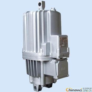
The electric hydraulic pusher is a transmission accessory that is often used in conjunction with a brake frame and is widely used for braking of various types of transmissions. It generally consists of two parts to drive the motor and the body (centrifugal pump). The body part is composed of a cover, a cylinder, a piston, an impeller and a turn. Electric hydraulic pushers are often used in conjunction with brake frames and are widely used for braking of all types of transmissions.
The electric hydraulic pusher consists of two parts, which drive the motor and the body (centrifugal pump). The body part is composed of a cover, a cylinder, a piston, an impeller and a turn. When energized, the motor drives the impeller and the impeller on the rotating shaft to rotate, generating pressure in the piston. Under the influence of this pressure, the oil is sucked from the upper part of the piston to the lower part of the piston, forcing the piston and the push rod and the beam fixed thereon to rise rapidly. . Mechanical movement is produced by mechanically compressing the load spring (the pusher or brake with a load spring) by means of a lever.
The electric hydraulic pusher is a transmission accessory that is often used in conjunction with a brake frame and is widely used for braking of various types of transmissions. It generally consists of two parts to drive the motor and the body (centrifugal pump). The body part is composed of a cover, a cylinder, a piston, an impeller and a turn. Electric hydraulic pushers are often used in conjunction with brake frames and are widely used for braking of all types of transmissions.
Working principle of electric hydraulic pusher
When energized, the motor drives the impeller and the impeller on the rotating shaft to rotate, generating pressure in the piston. Under the influence of this pressure, the oil is sucked from the upper part of the piston to the lower part of the piston, forcing the piston and the push rod and the beam fixed thereon to rise rapidly. . Mechanical movement is produced by mechanically compressing the load spring (the pusher or brake with a load spring) by means of a lever.
When the power is off, the impeller stops rotating, and the piston rapidly descends under the load spring force and its own gravity, forcing the oil to flow back into the upper part of the piston, and then returning to the original position by the lever mechanism.
Design features of electric hydraulic pushers
The electric hydraulic pusher shell is made of cast aluminum alloy, light in weight and beautiful in appearance; the motor is non-immersion oil type structure, B grade or F grade insulation (according to user requirements). The heat resistance is good and the service life is long; the motor junction box cover is sealed, and the cable stuffing box is used to enter the line, which is firm and reliable, and the electrical enclosure protection grade is IP55; the motor shaft and the push rod are plated with hard chrome, so that the seal life is greatly Extended; the cylinder housing is provided with a balancing chamber on one side, which allows the electric hydraulic pusher to be installed in any direction from 0 to 180°, thus expanding its range of use.
Contact: Li Jia
phone
Mobile phone
Website: http://
Http://jzzdqcj.chinawj.com.cn
Http://news.chinawj.com.cn
 Editor: (Hardware Business Network Information Center) http://news.chinawj.com.cn
Nickel based alloys are very useful materials for the manufacture of high quality tubing products. One of the key reasons is that they offer excellent corrosion resistance in both aqueous and high temperature applications.
In addition to their high melting points and resistance to oxidation and corrosion, nickel alloys are very ductile. They can be electroplated and are easily welded, making them suitable for use in industries where very high and low temperatures come into play.
Nickel alloys steel tube are excellent for heat exchangers in the chemical processing and nuclear industries. Nickel Alloy Steel Tube are used in steam generator tubing in the nuclear power industry, in high-temperature aircraft systems, and in oil and gas extraction programmes where corrosion, pressure and temperature resistant tubing is required. Nickel alloy steel tube corrosion resistance also makes them useful in desalination equipment.
Max Stainless Steel ( CNMAX) manufactures Nickel alloy steel tubes in the following nickel based alloys:
Alloy
UNS
WNR
200
N02200
2.4060
201
N02201
2.4061
C22
N06022
1.0402
31
N08031
1.4562
59
N06059
2.4605
75
N06075
2.4630
263
N07263
2.4650
C276
N10276
2.4819
400
N04400
2.436
600
06600
2.4816
625
N06625
2.4856
690
N06690
2.4642
825
N08825
2.4858
718
N07718
2.4668
800
N08800
1.4876
800H
N08810
1.4876
800HT
N08811
1.4959
Nickel Alloy Steel Tube
Nickel Alloy Steel Tube,Nickel Alloy Steel Pipe,Nickel Alloy Pipe,Alloy Steel Pipe
Zhejiang Max Stainless Steel Co.,Ltd , https://www.cnstainlesstube.com