
Multi-axis box modular design of combined machine tool based on UG(2)
2.2 Gear Design Module
Three gear design models are provided in the gear design module. The single gear three-dimensional design model establishes the gear model and the combined basic transmission model when designing the shaft. Now the combined basic transmission model is taken as an example to introduce the creation of the gear design module.
According to the different meshing modes between the gears in the transmission system, the common gear transmission assembly model library is established by the interactive modeling method of the system. There are three basic transmission models in the multi-axle transmission system of the combined machine tool: (1) the same row, one belt, one belt, two belts and one belt three; (2) different rows and two belts; (3) different rows and three belts. The drive system of the combined machine tool can be combined from the above four basic drive models.
The basic drive model module includes three parts: a graphics library, a database, and a master program. The graphics library includes a fully parameterized gear model. The coordinates of all drive shafts and spindles are stored in the database for input during calculation. The master program performs coordinate calculation, data access, and model update. In the combined machine design system, first number each drive shaft and spindle, and store the known axis coordinates in the database; then select the required basic drive model, calculate the unknown axis coordinates and store them in the database, and finally Modeling.
The main interface of the main control program is shown in Figure 3; the program flow is shown in Figure 4.
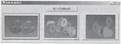
Figure 3 gear transmission design interface

Figure 4 main control program flow chart
The calculation process is illustrated by taking the dissipative belt and the two transmission model as an example. The two rows of two different gears are driven by two pairs of gears on one transmission shaft, as shown in Fig. 5. Knowing the coordinates of the O-axis and the A-axis and the number of teeth and the modulus of the transmission gear, the calculation process of the B-axis coordinate is as follows
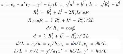
Figure 5 Calculation of one belt and two transmission models
The interface of the different row and two transmission calculation program is shown in Fig. 6.
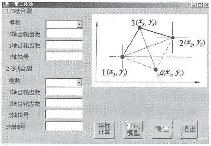
Figure 6 One belt two transmission calculation program interface
3 Conclusion
According to the overall scheme and design requirements of the multi-axle box of the combined machine tool, this paper divides and designs the function module of the multi-axis box. On the 3D software UG platform, using its powerful 3D modeling function and assembly function, the 3D of the multi-axis box module is established. Parametric model. The three-dimensional design method is used to replace the traditional two-dimensional design method, so that the design process is visualized, the design result is straightforward, and the design quality is improved. The modular design and 3D CAD system can greatly improve the design efficiency of the multi-axle box of the combined machine tool, improve the quality and life of the product, and ensure the success of product development.
Previous page
Plastic Sheet Machine,Plastic Board Machine,Plastic Sheet Extruder
Futian Machinery Co., Ltd. , http://www.skywin-extruder.com